
News
Kehui Electric Appliances·Service power
On-site verification process and common fault diagnosis for smart electricity meters
Release Date:2026-07-27
Power metering technology and management are critical to the timeliness and impartiality of national power generation, the stable operation of the entire power industry, as well as the legitimate rights and interests of the state and every power consumer. Both power supply companies and power users are involved in this system. Nowadays, industries dependent on power generation keep expanding their market share. According to the latest statistical report on China’s energy sector, China’s total electricity consumption reached approximately 6,844.9 billion kWh in 2018, representing an 8.5% year-on-year increase. Such enormous energy consumption makes the accuracy of electric energy metering more vital than ever. Apart from precise measurement via traditional power measuring instruments, on-site calibration of watt-hour meters must be adopted to ensure the accuracy of measuring equipment. First of all, appropriate power measuring devices shall be selected according to load conditions. In addition to inspection and verification before initial commissioning, regularly used on-site metering systems shall be inspected as required. With the gradual advancement of electric energy metering technology, old electromagnetic mechanical watt-hour meters have been phased out due to various drawbacks and replaced by electronic smart watt-hour meters. Smart meters feature higher measurement precision, smoother load curves, wider frequency bands, stronger overload capacity, low power consumption, superior environmental adaptability, long service life, accurate billing, and remote control capability. Taking electronic smart meters as the research object, this paper elaborates the whole process of on-site calibration and solutions to common faults.
1 On-Site Calibration Procedure for Smart Meters
1.1 Preparations for On-Site Calibration
Based on the calibration cycles for Class I, II and III watt-hour meters and the installation and operation duration of newly installed meters, adjust the quantity of on-site testing equipment and formulate the schedule for on-site watt-hour meter calibration. Prepare on-site tools and verify their completeness. Carry safety tools and other necessary supplies. Timely contact power consumption and maintenance departments to coordinate the schedule for on-site calibration.
1.2 Inspection Items for On-Site Calibration
① Visual inspection.② Verify the rationality of measuring point locations and calibration methods.③ Wiring inspection, including wiring between the meter and transformers, the tightness and corrosion status of meter screws, as well as the operating status and parameter performance of the meter.④ Reconciliation of combined readings of registers on fee-controlled watt-hour meters and deducted electric energy.⑤ Measurement error testing. After data acquisition, check the reading deviation between recording equipment and the watt-hour meter.
1.3 Operational Steps of On-Site Calibration
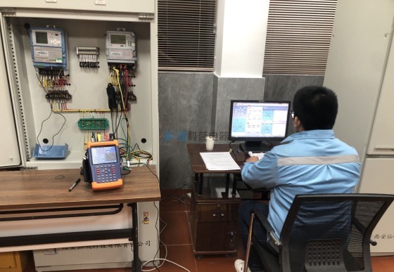
① Remove the lead seal of the terminal cover and confirm no loosening or corrosion of terminal posts.② Clamp the current sensing clamps of the calibrator onto the watt-hour meter terminals following conventional watt-hour meter wiring rules, and ensure correct phase sequence and polarity.③ Fasten voltage sampling clamps of the calibrator onto corresponding phase terminals inside the terminal cover: connect the neutral wire first, then the phase wires. Secure voltage leads to prevent slippage of sampling clamps during calibration. Switch on the on-site watt-hour meter calibrator and input relevant parameters. After entering the calibration interface, compare parameters displayed on the calibrator with readings shown on the watt-hour meter and implement load regulation. Check whether the phasor diagram is normal and the load remains stable.④ Adopt either photoelectric sampling or pulse sampling method to verify the fundamental error of the watt-hour meter. Upon confirmation, power off the on-site watt-hour meter and calibrator immediately.⑤ Remove voltage sampling clamps (disconnect phase wires first, then the neutral wire).⑥ Re-seal the terminal cover, arrange all tools and ensure no tools are left inside the terminal cover.
1.4 Analysis of On-Site Calibration Results
Check for damage to components of metering devices and ensure firm connections between meters and terminal covers to eliminate potential safety hazards. Identify unauthorized electricity consumption by users. Confirm that the watt-hour meter operates within normal parameters, metering deviations are within acceptable limits, and the meter remains within its valid calibration period.
2 Troubleshooting of Common Smart Meter Faults
2.1 Meter Burning Faults
Error analysis and investigation reports over recent years indicate that meter burnout is a dominant type of fault, which severely disrupts normal power supply service. Comparative analysis identifies several major causes of meter burnout:(1) Poor contact or overheating under heavy load on meter circuits;(2) Quality defects of printed circuit boards such as short circuits;(3) Human factors: for instance, insufficient tightening of terminal screws during installation increases contact resistance and causes meter overheating.Prolonged overload may lead to burnout of current sampling wires and built-in relays of the watt-hour meter. Heavy current at pulse output terminals burns out optocouplers. Improper neutral wiring at relay output terminals during installation may also result in meter circuit breakage.
2.2 Display Faults
Typical display failures of smart meters include missing display segments, incorrect readings and black screen, some of which are caused by human factors. Comparative analysis of malfunctioning meters shows that improperly inserted or cold-soldered LCD pins cause garbled display or missing segments; high temperature and humid operating environments may trigger the same problems.Poor soldering and tin plating defects on clock circuits lead to abnormal time display. The main causes of black screen faults are listed below:(1) Defective crystal soldering and unstable output of IC7805 voltage regulator that fails to meet operating load requirements;(2) Short circuit of capacitor C44 on the main board resulting in abnormal output of IC7805;(3) Abnormal conversion and intermittent winding output;(4) Power supply failure, which is also a major cause of meter malfunction.
2.3 Fee Control Issues during Operation
Principle of remote fee control: A network platform serves as the communication hub to calculate charges based on real meter data. Two categories of fee management faults are encountered: disqualification of remote controllers or failed ID authentication. Other faults include damaged encryption keys, incorrect security passwords and meter passwords transmitted during information exchange.Root causes include improper configuration of IP addresses, software passwords and port numbers in communication; power interruption occurring right after installing encryption keys and authentication devices, leaving meters unactivated; internal failure of the meter’s ESAM (Embedded Secure Access Module).Failure of remote fee control manifests as unsuccessful authentication, and commands sent by software to meters cannot be executed. Typical phenomena include meter crash without load shedding, or meter energization with unsuccessful tripping.Primary causes involve poor connection of control circuit components, loose switch structures under high temperature, defective moving parts, and relay faults. Relay failures mainly stem from contact damage, foreign residues inside relays generated during production, which cause pull-in and release anomalies. Instantaneous high current further burns out relays. Time mismatch between the meter’s display time and the operating system is another major reason for failed command execution. Time synchronization shall be completed prior to remote control operations.
2.4 Faults in Metering Process
Continuous flashing of the pulse indicator under fixed current and voltage signifies normal metering function. If no pulse output is detected on site, first inspect the wiring of pulse clamps, then measure the 4V pulse signal at pulse output terminals with a digital multimeter. If no signal is detected, the meter suffers from poor soldering or damaged electronic components at the pulse output port.Under rated current and voltage, absence of pulse output, indication and measurement may arise from widespread component defects such as poor soldering and component aging, inherent quality defects of circuit boards, incorrect wiring between conductors and terminals, excessive load current or poor contact. Meters may generate errors and irregular pulses under light load. Tests reveal that this is mainly caused by high-potential short-circuit between pins and high-level signals during pulse transmission inside the chip. When the chip transmits sampled data to the CPU, continuous accumulation occurs in the memory.
3 Conclusion
In summary, different types of faults vary in causes and occurrence frequency during the operation of smart meters. Maintenance and inspection technicians should master and strictly implement standard operating procedures to ensure all inspection and repair activities comply with standardized technical specifications. This guarantees reliable performance of smart watt-hour meters, achieves long-term stable and safe operation, and delivers better services to power users.
Zhuhai Kehui Electric Appliance Co., LTD
Tel:+8613794192106
QQ:1592428365
Email:1592428365@qq.com
Youtube:@user-zz7de3pk6c
SKype:live:.cid.f6f23d31ff6b29ee /name:Wendy ShenSyyglobal23@gmail.com
Copyright © 2026 Zhuhai Kehui Electric Appliance Co., LTD